 | ||||
HOME | ESR Meters | LCR Meters | Continuity-Low Ohm Meter |Geiger Counters | Tektronix | Metal Detectors | Contact Projects | Other Lab Tools | Solar | Master-Slave Switch | Semiconductor | ||||
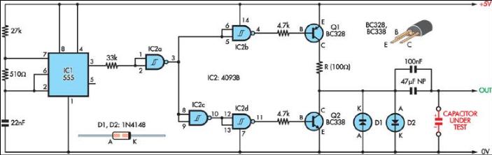 | ||
When teamed up with an oscilloscope, this simple circuit provides a means of measuring capacitor ESR. A 555 timer (IC1) configured as a 2.3kHz free-running oscillator acts as the timebase. It provides narrow (7.7µs) pulses to the capacitor under test via a NAND Schmitt trigger (IC2) and transistor Q1. A 100Ω resistor in series with Q1 limits current flow to about 50mA. Therefore, an ESR of 1Ω will produce pulses across the test capacitor of 50mV, which means that an oscilloscope with a vertical sensitivity of 5mV can measure ESR down to 0.1Ω or less. Transistor Q2 discharges the test capacitor during the "off" portion of the test cycle, ensuring a zero average DC component. Diodes D1 and D2 limit the maximum output voltage to approximately 0.6V, corresponding to an ESR of 12Ω, which is adequate for most uses. If accuracy is not critical, then the circuit could be powered from four AA batteries rather than from a regulated 5V supply. Finally, despite building this circuit, I did invest in the ESR meter described in the March and April 2004 issues of SILICON CHIP! Graham Jackman | ||
Silicon Chip Bare Bone ESR Meter with output on a scope
published December 2004